

1. Introduction
Lightning impulse testing is a mandatory dielectric type and routine test that proves a power transformer can withstand the steep, high-magnitude voltage surges caused by lightning strokes and switching operations on an overhead transmission system. For a 15 MVA power transformer, the insulation system must be verified against the specified Basic Impulse Level (BIL), which for this unit is 170 kV peak. This article describes the test setup, the applied waveform, the interpretation of the recorded Oscillograms, and the acceptance criteria used to confirm the integrity of the winding insulation.
2. Transformer Rating and Test Voltages
The device under test is an oil-immersed, ONAN-cooled three-phase step-down transformer. The key nameplate data and the associated dielectric test voltages are summarised below. The 170 kV BIL is applied as the full-wave lightning impulse, while the switching impulse and power-frequency withstand values confirm the overall insulation coordination.
|
Parameter |
Value |
Standard / Remark |
|
Rated power |
15 MVA |
ONAN / ONAN cooling |
|
Rated voltages (HV / LV) |
110 kV / 33 kV |
Three-phase, 50 Hz |
|
Basic Impulse Level (BIL) |
170 kV |
Full-wave, 1.2/50 µs |
|
LI test voltage (peak) |
170 kV |
IEC 60076-3 / IEC 60060-1 |
|
Chopped-wave impulse |
187 kV (170 × 1.10) |
Crest not less than 170 kV |
|
Switching impulse (SI) |
117 kV |
250/2500 µs |
|
Applied voltage withstand |
5.5 kV / 95 kV |
Exciting-winding / induced |
|
Power-frequency withstand |
140 kV RMS |
Separate-source AC |
|
Impulse generator |
600 kV, 20 kJ |
8-stage Marx generator |
Table 1 - Nameplate rating and dielectric test voltages for the 15 MVA transformer.
3. Objective and Applicable Standards
The objective is to demonstrate that the transformer insulation can withstand the specified BIL without breakdown, and to detect any internal insulation weakness. The test is performed in accordance with IEC 60076-3 (Power transformers - Insulation levels, dielectric tests) and IEC 60060-1 (High-voltage test techniques). A digital impulse measurement system records the voltage and the transient current through the neutral, producing the Oscillograms used for evaluation.
4. Test Setup and Circuit
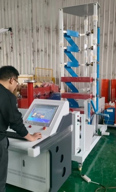
The impulse is generated by a multi-stage Marx generator of 600 kV / 20 kJ and applied to the high-voltage (HV) terminal. The neutral is earthed through a low-inductance current shunt, and the LV winding is short-circuited and grounded. A damped-capacitive voltage divider delivers the voltage signal to the digital recorder. The essential arrangement is:
Impulse generator: 8-stage Marx, wavefront shaping resistors producing a 1.2/50 µs standard wave.
Voltage divider: damped-capacitive divider, calibrated per IEC 60060-2.
Current measurement: low-inductance shunt at the neutral for transient-current recording.
Recording: digital recorder, sampling rate ≥ 100 MS/s, for accurate front-time capture.
Sequence: one calibrated wave, then three full waves at 170 kV, negative polarity.
5. Impulse Waveform and Parameters
The standard lightning impulse has a virtual front time of 1.2 µs and a time to half-value of 50 µs (designated 1.2/50 µs). The recorded Oscillograms must be analysed for the peak value, front time, and time to half-value. Deviations such as overshoot, oscillation, or a distorted tail wave may indicate winding resonance or partial breakdown.
Peak value: 170 kV ± 3 % tolerance allowed.
Front time T1: 1.2 µs ± 30 %.
Time to half-value T2: 50 µs ± 20 %.
Polarity: negative (as specified by the standard).
6. Interpretation of the Oscillograms
The Oscillograms are the primary evidence of insulation integrity. A healthy transformer produces a smooth, single-peaked voltage wave and a corresponding neutral-current trace consisting of a sharp initial capacitive spike followed by low, decaying oscillations. Comparison is made against a reduced-voltage reference wave (typically 50–75 % of the full BIL). The following signatures are evaluated:
*Normal record - unchanged wave shape from reference; no abrupt collapse of voltage.
*Winding insulation breakdown - sudden voltage drop or chopped wave followed by high sustained current.
*Partial discharge / turn-to-turn fault - distortion of the tail and increased high-frequency oscillation.
*Shifted or damped wave - possible series or shunt impedance fault; requires investigation.
7. Acceptance Criteria
The test is considered successful when all three full waves at 170 kV show no evidence of breakdown. The current Oscillograms must be identical in shape to the reference record apart from the expected amplitude scaling. Any change exceeding the noise tolerance, in either the voltage or the current trace, requires repetition of the test and, if confirmed, internal inspection of the winding.
Lightning impulse testing at a 170 kV BIL provides a decisive verification of the insulation strength of the 15 MVA transformer. By combining rigorous waveform control with careful analysis of the recorded Oscillograms, manufacturers and utilities can confirm that the transformer will reliably withstand lightning overvoltages in service and satisfy the requirements of IEC 60076-3.